1. The RGB LED Panels
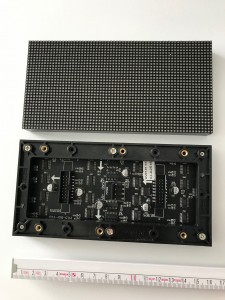
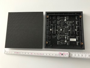
The panels we use are sold for video walls and advertising signs. There are many sizes of panels available with different spacing between the LEDs. The ones that fit best into a pinball have 2.5mm spacing (also referred to as P2.5), which results in a 128×32 display of 320×76.8mm. This can be mounted into an existing DMD/speaker panel from a pinball cabinet. Currently the only place to buy these panels is from AliExpress. Make sure that you end up with panels which have 1/16 scan and HUB75 pinout since this is the only type currently supported by PIN2DMD for 128×32 displays. The good thing is that they are seamless. To build a replacement display for Sega 192×64 you need three 64×64 panels with 2.0mm spacing (P2) . These panels measure 128x128mm and result in a total display size of 128x384mm which is nearly the same size as the original Sega panels. You need a Nucleo-144 based controller with V4 shield to run this configuration. For HD 256×64 you need two 128×64 panels with 1.875 spacing (P1.875). These panels measure 120x240mm and result in a total display size of 120x480mm. Make sure you get panels with NON-PWM chipset like MBI5124, ICN2037, ICN2038, FM6124,FM6126, FM6127 etc.
PWM chipsets like MBI5153, ICND2153, LYD6168, FM6353 are currently not supported.
P2.5 160x80mm RGB LED Panels P2 128x128mm RGB LED Panels
2. The Controller
2.1 The STM32F4 Nucleo board with PIN2DMD shield (DIY)
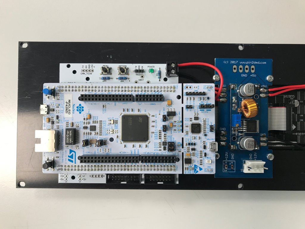
The panels use a 16 pin Hub75 interface to be connected to the next panel or to a controller. We use a STM32F4 Nucleo-144 (NUCLEO-F429ZI or NUCLEO-F439ZI) board (V4 shield) which is available from multiple sources for about $20. Please make sure you buy a genuine STM board. Cheap chinese copies may cause problems and are not supported. Those boards are based on Cortex M4 processor architecture which is needed for the rapid bit-shifting of data to control the panels. We write the program in C/C++. The software is uploaded to the controller through debugging USB port using ST-Link Utility or in DFU mode.
To connect the displays to the controller you need a connector shield pcb, which basically just connects the pins to the 16-pin ribbon cable that drives the displays. The board also has a 14pin connector which can be as input to get the data from a real machine. A PCB layout example can be found in the hardware directory here. The advantage of the modular system is that new hardware functions can easily be implemented by changing the shield while keeping the controller. Members of the community have organized a group buy for printed circuit boards and also offer different kits. Search for PIN2DMD on german flippermarkt forum or VPUniverse forum .
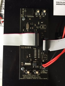
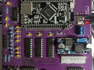
Picture of the STM32F429 Nucleo-144 board with V4 shield and DC-DC converter PCB
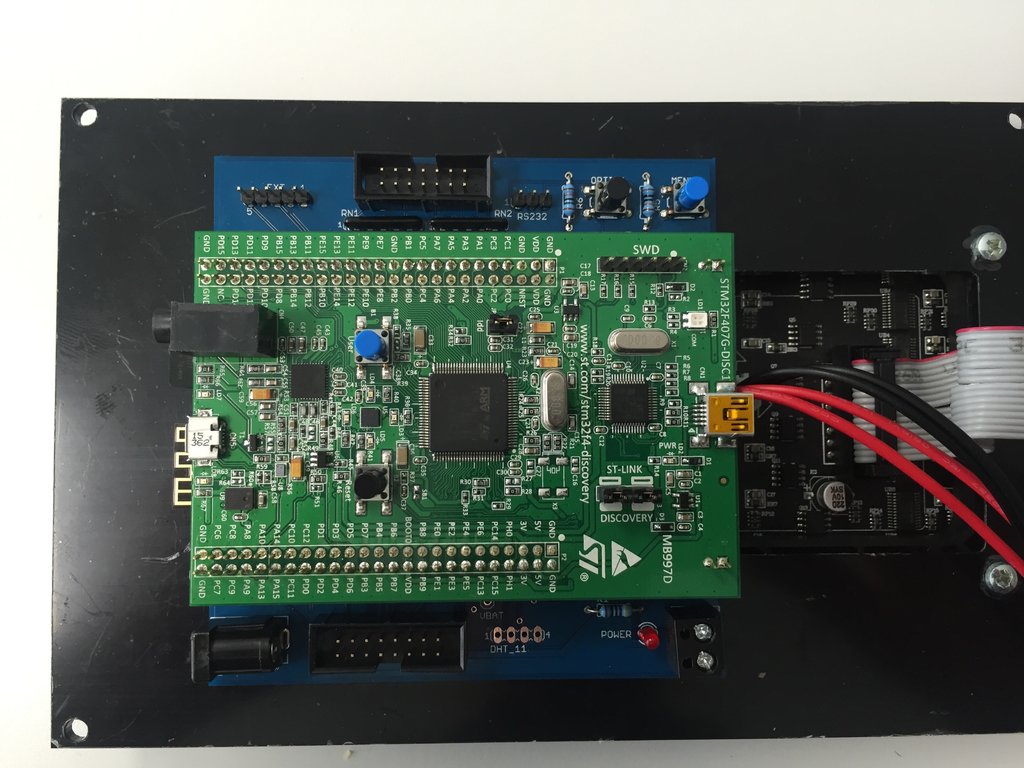
Picture of the deprecated design based on a STM32F407 discovery board with V3 Shield.
Don´t use for new pin2dmd builds. Activation no longer possible.
2.2 The STM32H743VIT6 DevEBox board with PIN2DMD HD shield (DIY)
Just like the shield pcb above for the 128×32 and 192×64 displays there is a shield for the 256×64 HD PIN2DMD. A PCB layout example can be found in the hardware directory here. It is based on the cheap STM32H743VIT6 DevEBox board which is available from various sources on AliExpress or ebay. The pcb can be ordered from PCB assembly services like pcbway.com or elecrow.com.
2.3 The custom made EVO boards
To have a more professional look we designed a all-in-one pcb board which integrates the controller board, shield and DC-DC power converter on one PCB. It is based on the latest Nucleo V4 schematics. It can be ordered from PCB assembly services like pcbway.com or elecrow.com. You only need to solder the power cables for the panels and mount the RGB panels. All the necessary order information can be found here. Members of the community have organized a group buy evo boards. Search for PIN2DMD EVO on german flippermarkt forum or VPUniverse forum .
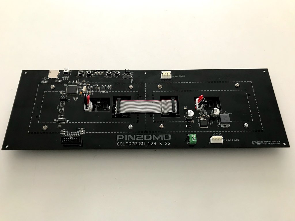
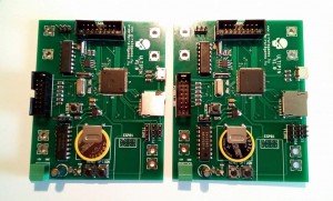
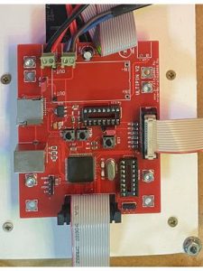
Picture of the EVO128x32 board
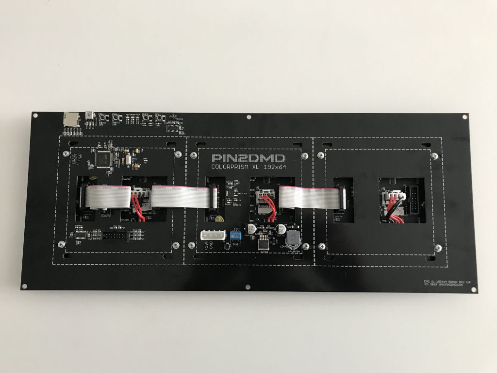
Picture of the EVO192x64 board
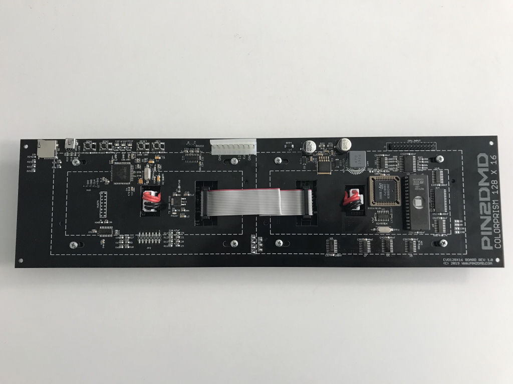
Picture of the EVO128x16 board
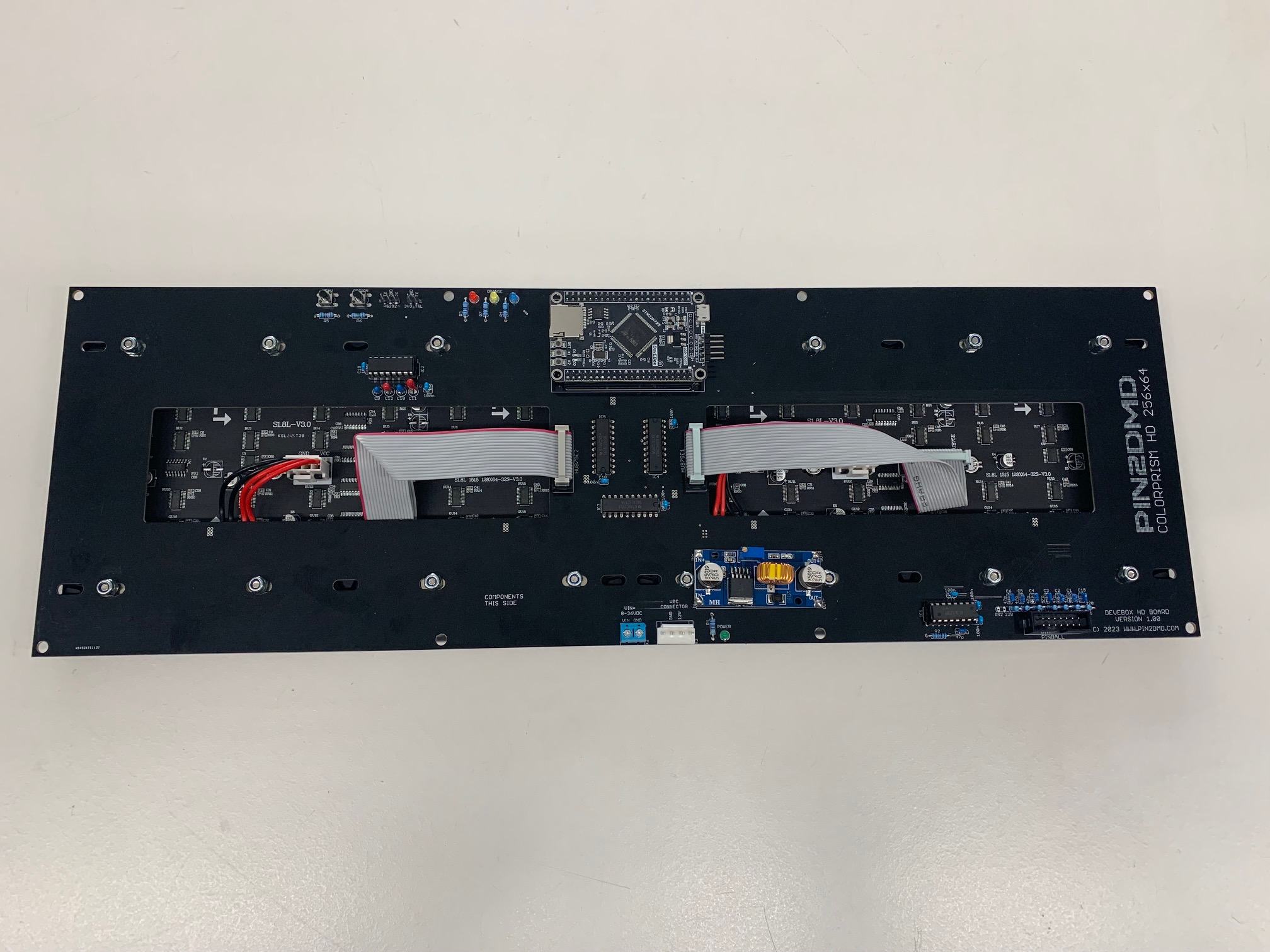
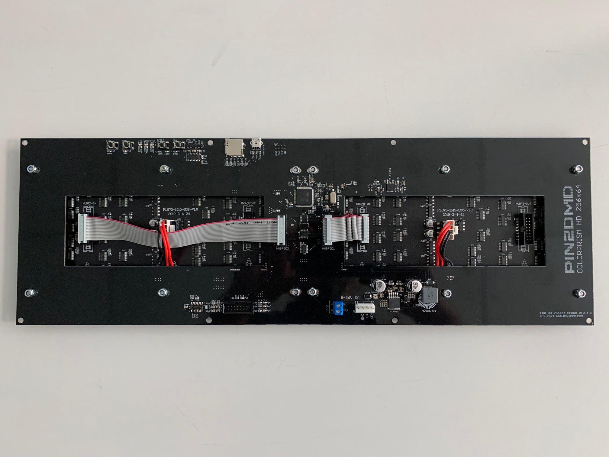
Picture of the EVO256x64 board
2.4 Custom hardware from 3rd party manufacturers
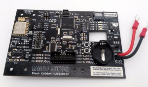
Some members of the pinball community design their own custom hardware based on our published schematics. Some of them even blatantly violate our license to avoid having to contribute to the charity projects we support (children with cancer, orphans, children in a hospice because they lost their parents or will die, etc). Please understand that we can not give any support for these hardware designs and can not guarantee that they will work with future releases of pin2dmd. We develop and test our firmware exclusively on our hardware designs presented above. So if you want to make sure that your pin2dmd display will work in the future, make sure you get one of the above boards. If you have any problems with custom designed boards, please contact the designer/manufacturer of those boards. For custom designed boards that are based on the deprecated STM32F407 discovery board design, the last activation date was 31.12.2020. There is no possibility to activate such a board after that date. Here are some examples of custom designed boards which are not officially supported by us.
3. The Power Supply
The RGB LED displays require 5vdc for power and if you want to run them with full brightness they need a lot of current. A 5A power should be enough. You need to connect that power supply up to both panels. You can also use 5A DC-DC 12 to 5V converters for real pinball machines.Please make sure the power is adjusted to 4.8V before you use them. The EVO PCBs have a DC-DC converter circuit onboard.
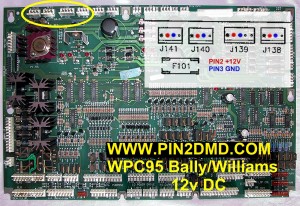
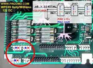
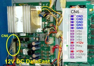
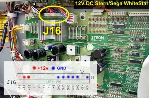
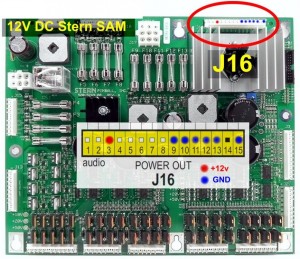
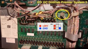
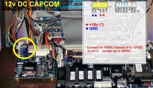
Important !!! Please NEVER use the 5V rail from your pinball machine or the 12V from the original DMD power connector. You are risking to overload and destroy your pinball hardware if you do so. On e.g. WPC machines the 12V on the original DMD power connector can only supply up to 1A, which is not enough for a pin2dmd. Please check your pinball schematics before connecting to a internal 12V power source.
Here are some examples of where to get power for the DC-DC converter from.
4. The Frame
For perfect alignment of the panels side by side a laser cut frame is recommended. (Not needed for EVO boards) Sample layouts can also be found on github here