1 General concepts
The pin2dmd editor is developed for creating your own personal colorized dmd experience when playing virtual pinball or real pinballs. Its only usable with the pin2dmd controller device (beside a minor use case for the older goDMD clock).
The get colorized dmd experience you can:
- change the default palette
- define additional palettes
- create scenes with your own content and higher color resolution for playback
- add content / color to dynamic scenes e.g. score display (please don´t use copyrighted material for colorizations)
- trigger automatic switching of palettes based on „key frames“
- trigger playback of replacement scenes based on „key frames“
- trigger for playback of added content to dynamic scenes
- define a mask, so that only part of the dmd is taken into account for triggers
Beside these major use cases there is a couple of tooling around the pin2dmd device, that allows configuring and preview and so on.
2 Menu
Short descriptions of the main menu items.
2.1 File
2.1.1 Load / Save Project
Load and save complete editor projects. Project file is store in xml and more or less human readable. It contains palettes, key frames and mask. It also contains references to all loaded animations. Therefore loaded animations should always copied with the project file itself.
When saving project that includes „cutted“ scenes (and therefore new ones) an new *.ani file will be saved with the project. As said before these files should always be moved with the project, so that xml and *.ani files always stay together.
2.1.2 Import Project
Basicly the same as load project, but all entities like key frames, animations and scenes are added to the current project.
2.1.3 Export Project for real Pinball machines
Export the project for use with the pin2dmd controller. This action requires a license (see licensing). When exporting one or two files are created, that have to be copied on the devices micro sd card.
The *.pal file contains palettes, mask and key frames definitions. When you create colorized scenes a *.fsq file is created which holds all the scene data. Please don´t share your project if you use copyrighted content for your personal colorization.
Remember: in order to get recognized by the device both files need to be named: pin2dmd.pal and pin2dmd.fsq respectively.
There is also the alternative to directly upload to the sd card of the device, if the computer running the editor is connected via usb with the pin2dmd controller.
2.1.4 Export Project for virtual Pinball machines
When exporting one or two files are created, that have to be copied to your pinmame altcolor folder structure. Create a subdirectory with the rom filename you want to use the colorization with and copy the files named pin2dmd.pal and pin2dmd.vni to that folder.
The *.pal file contains palettes, mask and key frames definitions. When you create colorized scenes a *.vni file is created which holds all the scene data. Please don´t share your project if you use copyrighted content for your personal colorization.
2.2 Edit
2.2.1 Undo / Redo
Just the usual undo / redo functionality, but for the editor this only effects drawing in replacement scenes. Same can be achieved with buttons on the main window.
2.3 Animations
2.3.1 Load Animation
Loads all kind of animations to work with. Animations are added to the current project and will appear in the animations list. About animations formats see chapter animations.
2.3.2 Save Animation
Saves all animations in the animations list in one *.ani file.
2.3.3 Export Animation as Gif
Save the selected animation as animated gif image.
2.4 Palette / Modes
2.4.1 Load /Save Palette
Loads palette data from pin2dmd editors xml format or from smartdmd text format. Saves xml format.
2.4.2 Create Device File / WiFi
Creates a device file (pin2dmd.dat) for use on the device micro sd card (real pinball). You have to select mode of operation and default palette.
His dialog window also include configuration of the pin2dmd hostname, if the pin2dmd device is shipped with wifi support.
2.4.3 Configure Device
Offers various configurations for live configuration of the device. Works only if your computer is connected via usb with the device or the correct hostname was configured when device is shipped with wifi support.
You can switch palette, upload you license to be stored on the device flash memory (only if you have already registered your editor), reset the device and switching operation mode.
2.5 Help
2.5.1 Get Help
Open help page on the web (this page)
2.5.2 Register
Allows you to register your license (or key file) with the editor. This will enable all actions the require a license (actually only export or upload project).
Register al license is also a precondition to enable the upload of the license to the device directly.
The location of the license file is kept in a properties file (pin2dmd.properties) in the users home directory. So please do not delete pin2dmd.properties or do not move the key / license file.
Of course you can delete both and always reregister a new one. But remember license files are specific to each devices unique identifier.
2.5.3 About
Opens about dialog that displays the version, build date and build number. This is useful for error reports to include, so developers can be sure which build your are using.
3 Main window
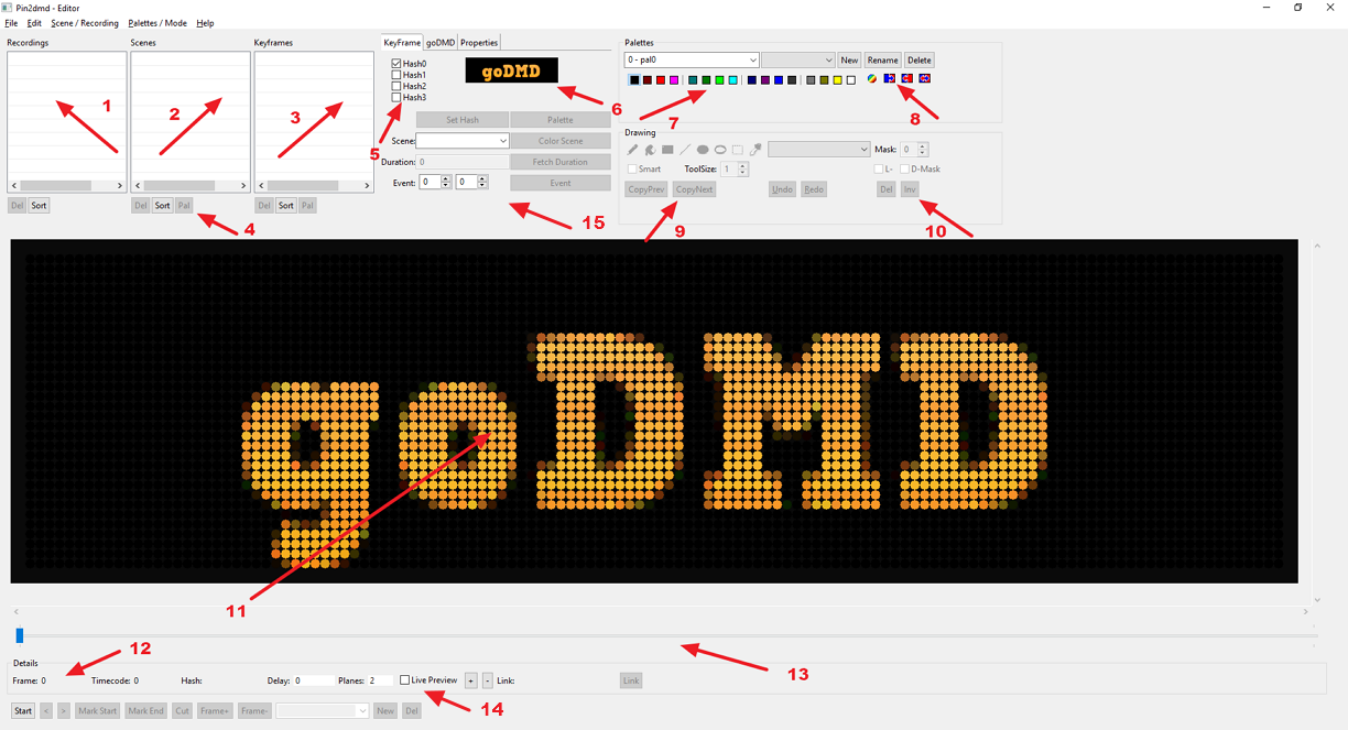 Image: 1
- The recording list. Contains all loaded recordings. When you select one, it will be displayed / shown in the preview.
- The scene list. Contains all scenes which are normally cut from recordings and then edited. You can also rename an animation. Simply click on an row, edit name and press return.
Deselect a row by pressing esc key. - The key frame list. Holds all key frames defined in your project. Key frame reference the crc checksum of a frame (or specifically a plane) of an animation. You can rename key frame same way as animations. Esc key deselects a row. When you click on a key frame, preview jumps to animation where you define the key frame. Also the palette gets selected. To change palette or duration, simply select key frame, do your changes and select another key frame (or deselect).
- Action buttons for animations: Remove: removes the selected animation (no warnings, not undoable), Sort: sorts animations by name.
- The actual crc checksum for the current frame. If frame has 2 planes, then 2 checksums are active. Also 4 planes gives 4 checksums. Checkbox on the left marks which plane will used for key frame detection. If plane is empty (all black) crc becomes inactive.
- Plane preview for key frame definition. Show the same frame as the big preview 11, but only the selected plane. One can use this as hint to find the best plane for triggering. e.g. if dmd frame contains „background noise“ like stars you can easily find the plane that is „clear“ to be used as trigger.
- Palette (CTRL-click to edit colors and SHIFT-click to swap)
- Palette tools like create gradient, swap /copy / paste color swatch
- Drawing tools (see drawing and colorization)
- Mask selection and enable mask drawing
- Big preview panel for DMD that shows the actual scene / frame. Can be zoomed in and out via the + and – buttons on the right. One can slide through the scene using the big slider below or playback the scene in realtime (start / stop button)
- Detail view for frame number, time code (in millis since start of the scene), delay (time span between this frame and the last frame) and the number of planes.
- Slider to scroll through the scene
- Live Preview switch, if checked and computer is connected to pin2dmd controller, everything that is show in the preview is also shown on the LED panels. This allows much better control of coloring.
- Key frame controls for creating / editing / removing key frames.
3.1 Key frames
Key frames define trigger points where something should happen: either switching of palette, start replay of a sequence of frames that replaces the original ones or add content to the frames coming from the pinball. A key frame is defined by its checksum (shown at 1) and its action (what should happen).
Checksums are calculated separately for each plane. If the plane is all black, the checksum at 1 will be disabled. The small black and white preview DMD shows the just the selected plane. This can be useful to find the best plane to trigger.
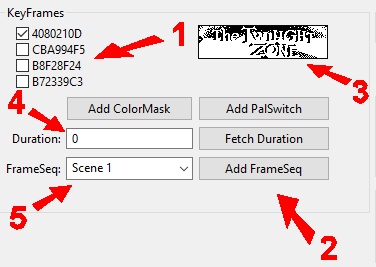
Image: 2
Also checksums are influenced by the mask (see below). If a non standard mask is defined for a project, only point that are not masked out are taken into account, when calculating the checksum.
To create a key frame there are two action buttons below 3:
-
Add Palswitch: defines a key frame starting at current displayed frame, that switches the palette.
-
Add FrameSeq: defines a keyframe starting at the current displayed frames, that starts the chosen frames sequence. Sequence must be selected at 5 before clicking “Add FrameSeq”
- Add ColorMask: defines a keyframe starting at the current displayed frames, that starts the playback of additional content. Sequence must be selected at 5 before clicking “Add ColorMask”
After you defined a key frame for palette switching there is another option to choose: the duration.
Duration can left blank / 0 then the palette will hold as long as a new switch is triggered. Or you can enter a time in milliseconds. To make it easy to determine the time, you can also slide the current animation that should receive the new palette to its end and then click “Fetch duration”. In this case exactly the time between starting point (key frame definition) and the current point will be inserted in the duration field. Changes to duration and palette will always saved if you switch to another key frame.
When you define a FrameSeq with a key frame, duration is meaningless. Frame sequences are always played to the end.
3.1.1 Mask
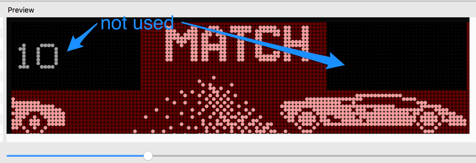
Image: 3
When you check the mask checkbox in the main screen, a red overlay over the current scene will appear. Initially it covers the complete screen. You can now you the usual draw tools to draw a customs mask. Of course there are only two colors available while in mask mode. As shown in the picture above everything that is not covered with red is masked out. This means pixels in the black areas do not contribute to the checksum of key frames.
Actually there is only one mask per project and therefore this mask has a global scope for the whole game. Another important thing to mention: actually the checksum is calculated only once right in the moment when you press the button. If you change the mask later on, you have to redefine your key frames. There is no automatic recalculation of the checksum when mask changes. (this will maybe improve eventually)
3.2 Palettes
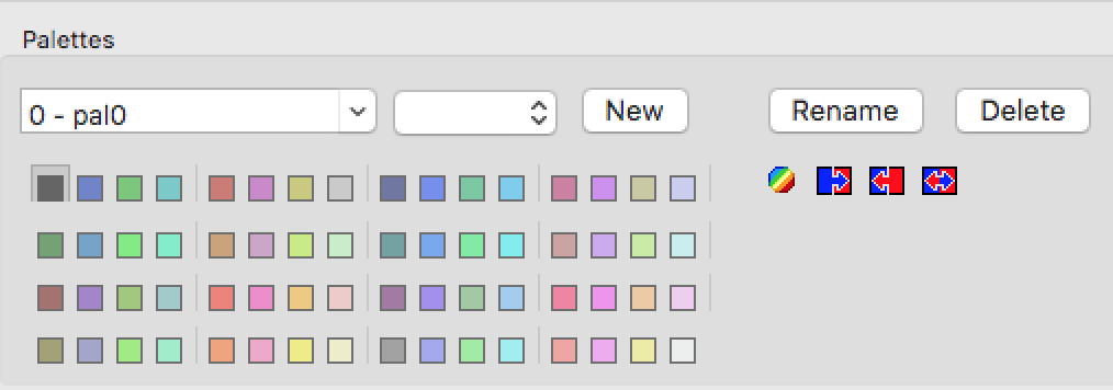
Image: 4
Palettes define up to 64 colors out of a true color space, while the actual firmware support color depth of 18bits which means 262.144 different colors.
You can edit the individual colors through CTRL-click.
There two types of palettes: default and normal. The default is simply the one that is switched back, when timed palette switches are timed out and of course the palette to start with.
You can also rename palettes by simply click into the combo box and the press rename. Always start your name with “<number> – “ because each palette has an index number which is the first part of the name. You can define as many palettes as you want (up to out of memory on the controller at least).
New button creates a new palette based on the colors of the actual one.
Apply button changes the palette of selected keyframe to the current palette.
Palette Menu also allows to load and save palette separately from the whole project. Import also can read smartdmd.txt files which holds all the palette information used for smartdmd projects.
Depending on the current animation displayed, there are only four colors active (0,1,4,15). To enable all 16 colors the current animation must have 4 planes.
3.3 Drawing and colorization
To add more colors to a scene you need to cut a existing scene from a dump file using mark start / mark end / cut.
Replacement mode you can edit / change every pixel of the current picture.
You can even use prerecorded videos or animations for playback.
A replacement scene is not bound / synced to the frames coming from the pinball machine. It has its own timing. If you want to have frame sync replacement you need cut the replacement scene into single frames and assign a keyframe to each frame. Please don´t use copyrighted material if you publish your project !
In ColMask mode you can only add content or color to the existing content. You can modify the colors of areas by assigning a different color group. Depending on the number of shades coming from the pinball machine, you have either groups of 4 colors or groups of 16 colors here.
You need to play with the palette colors a little bit to get comfortable with that feature. By combining the detection mask with the color mask you are able to add color to dynamic content like score display etc.
When an editable scene is displayed / selected, drawing toolbar becomes active. You can then use drawing tools (2) to recolor the scene frame by frame. The drawing tools itself are rather self explaining the last one with the palette icon is not yet finished and does nothing right now.
To change a color (1) simply use Ctrl-Click (or CMD-Click on mac) to open the color picker.
4 Color Picker
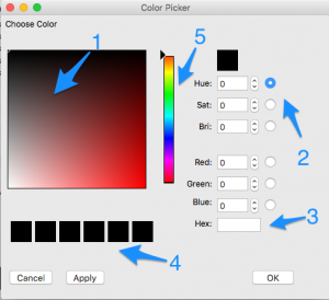
Image: 6
- main select area just click and move mouse to choose color
- radio buttons that control which value is to set by slider 5
- hex value for color, can also be used as input to set color
- recently choosen color, simply click on on one to restore old color
- slider controlling hue, saturation, brightness or r g b, depending on radio buttons 2
For „Apply“ the color picker stays open and palette value will be changed permanently. You can then choose another color from palette and change it.
5 Animations
Animations are a sequence of images that fit for displaying it on a dmd. Animations can be loaded from:
- vpinmame recording
- real pinball recording
- *.ani files (the editors own animation file format)
- various other sources like a batch of images, an animated gif and more
Most of the „normal“ animation formats are simply recognized by the file extension. E.g. *.txt or *.txt.gz stands for vpinmame recordings, *.ani for pin2dmd editor animations.
Every other source is „described“ by a property file and therefore you load the animation by „loading“ the describing property file.
Most of this functionality was derived from the former goDMD editor, so a couple of options described later is simply useless for pin2dmd and can be ignored.
5.1 Recording animations with Visual Pinball
To get recordings from a vp session you need to install Visual Pinball and a special version of vpinmame.
The basic steps are:
- To get a dump use the latest vpinmame version.
- generate a subfolder called “dmddump” in your pinmame folder.
- activate the dump by checking “Use external DMD” and “Show DMD Window” in the Game Settings together.
- play your favourite pinball and try to include as many dmd frames as possible.
- locate the dump file in your tables folder named <tablename>_dump.txt and compress it with gzip (http://www.gzip.org) or any other compressor able to generate .gzip files.
- Use the recording with the editor.
5.2 Recording animations from real pinball machines
To get recordings from a real pinball machine you need a active USB connection from the micro USB port of your pin2dmd controller to a PC / Laptop. The pin2dmd.exe tool needs to be installed on that PC. If the connection is working properly you should be able to set colors and mode of the device on-the-fly. If you check the “create dumpfile” checkbox a dump.txt file is generated in the working directory of pin2dmd.exe. This file needs to be compressed using gzip for the use with the editor.
Best practice is to remove the playfield glass and throw the pinball to activate
the different modes and animations. That way you can get a complete recording of a gameplay from your pinball machine.
5.3 Describing animations (only goDMD)
File format follows the standards for Property files in Java, so lines begin with “name” or Keys, followed by an equal sign “=” followed by a value.
Besides a few general keys at the beginning of the file, the keys always have a period in their name. On the left side of the point is the name of the animation, on the right the name of the property.
Example: logo.start = 1
The animation is “logo” and the start attribute has the value 1.
Important: if you define more than one animation in a properties file, all animations must be clearly identified. So every animation name must be unique.
An animation can be created from different sources:
- a sequence of images with the resolution 128 × 32 (various format like PNG, JPG ..)
- a DMDF file
- an animated GIF with the resolution 128 × 32
- movie formats (requires a editor extension)
Each animation has a section in the property file that describes the animation. Path information is always relative to the base path. If nothing else is said is the base path identical to the program directory.
Note: again as said before many keys are only meaningful for use with the goDMD clock and can be ignored for use with pin2dmd.
5.4 Available Keys and their meaning (only goDMD)
Below I always use the name of the animation “ani” (eg ani.start = …). But please remember that for more animations, different names must be used. Name are sensitive, so “Ani.start” is not the same as “ani.start”
ani.path: the file path is under to find the image sequence / image. Relative to the base path.ani.start: number of the picture with the animation starts. This may not necessarily be the one, if the directory contains more frames than this animation includeani.end: number of the picture with the animation ends. Start and end can also specify in hexadecimal. eg 0x0A for 10 s.ani.step: increment when counting up the image sequence. Are you here to 2, only every second image animation is added added.ani.hold: number of steps that is before again switched at the end to watch the animation, should remain.ani.millisPerCycle: wait time in milliseconds from one image to the next. Determines the speed of Animaton. Reasonable values are 100 or greater.ani.cycles: An animation can be repeated before again switched to the clock. For run twice for is ani.cycles = 2, etc.ani.type: symbol of the resource type beschreibt`: PNG for PNG image sequence, GIF for Animated gif, DMDF for DMDF File.ani.clockFrom: if set, if defines the no of the image, when the clock will reapper again. e.g if the animation has 10 frames clockFrom = 5 will let the clock reappear in half of the animation.ani.clockSmall: If set to true, while the animation a small clock display (smaller font). Default is large.ani.fsk:defines the age limit for this animation. If the scene is not suitable for children, then please here 18 or 16 running. Possible values 18,16,12 and 6. Default 16thani.clockInFront: If set to true, during the animation, the clock is displayed in front, without “cutting” the mask. Depending on the animation fits front or behind it better.Default is in the foreground. Only works together with clock from.ani.clockXOffsetandani.clockYOffset: to use only small letters of the watch during the animation. Defines the location where the clock is displayed.ani.clockFront: If set to true, then the clock appears during the animation in the foreground and not behind it. Only together with clock from.ani.thresholds.0, ani.thresholds.1andani.thresholds.3defines three levels of brightness between 0 and 255, which are used to convert color or images with many shades of gray on the DMD with its four colors. one need only the PNG or GIF if the images are generally too light or too dark. Alternatively, you could also change the images with which an image processing program.ani.autoMerge: If set to true along with step = 2, then two successive images are combined to form a composite. The first picture will download the brightness level 1, the second stage 2 images which are extracted directly to a ROM, are right in front in this format, so you can deal with them directly with this switch.ani.pattern: specifies the name pattern determined as the files of the image series are named. It always seems a “% placeholder” for the serial number. Example “logo% d” becomes “logo1.png”, “logo2.png” etc. Uses are only two “% d” or “% 04X”. Who wants to know exactly what you can do with it, should look under “Java String Formatter”.
6 Register license
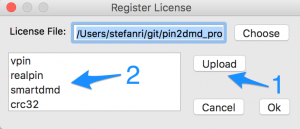
Image: 7
With this dialog window you can register a license / key file with your editor. Simply choose key file with file chooser and it will be installed. The location of the license file is stored in a pin2dmd.properties file in the users home directory. In a windows environment this is typically C:\Users\<your name>.
If you delete this file or move the key file to another location, you have to reregister the editor.
The upload button (1) uploads the activation key file to the pin2dmd controller and writes it into the flash memory of the controller. Therefore to activate the firmware on your controller you have to do this only once. Another tool to activate with a key is pin2dmd.exe which is also available on github.
The area (2) shows the capabilities included in the key file. To use the editors export / upload functions you have to have at least “vpin” or “realpin” or both.
7 Device config
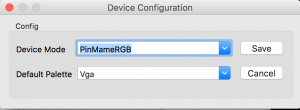
Image: 8
The dialog window allows the creation of a basic config file pin2dmd.dat for use with real pinball machines. Simply choose device mode and default palette for your machine, press save and store the resulting file onto the pin2dmd controllers sd card.
8 USB config
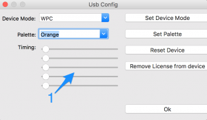
Image: 9
This dial window allows many different actions to an usb connected pin2dmd controller. You can change palettes, switch device mode or reset the whole device. Everything is applied immediately while the controller is running.
You can also remove a license which was written to the controllers flash memory before. Be careful with this function its not reversible, so you have to have a matching key file for this controllers uid to upload a license again.
9 Appendix: file formats
9.1 Animations *.ani
This files holds one or more animations and its frame data. It is the „native“ format for the editor. All numbers are stored in “BIG_ENDIAN” order, that means most significant byte first.
Structure of the file:
4 Byte Header: ANIM
2 Byte Version: 00 01
2 Byte Anzahl der Animationen: 00 02
N Byte Name der Animation in modified UTF-8
   first 2 Byte gives length of string incl 2 byte length header
2 Byte: cycles
2 Byte: hold
2 Byte: clockFrom
1 Byte: clock small
1 Byte: clock in front
2 Byte: xoffset for small clock
2 Byte: yoffset for small clock
2 Byte: refresh delay in millis
1 Byte: Animation Type (not relevant)
1 Byte: fsk tag
2 Byte: frame set count


each frame consists of 2 or 3 planes and optionally a mask plane
each plane is tagged with its type 0,1,2 for normal bitplanes in
grayscale animations or M ( for mask, the order is always m,0,1,2
where m and 2 are optional

foreach frame:
    2 Byte: plane size in Byte. normally 512 byte
    2 Byte: frame duration in ms
    1 Byte: number of planes
    foreach plane:
        1 Byte: type of plane, m,0,1,2 see above
        plane size Byte frame data: 1 Bit = 1 Pixel
        Bit 7 is pixel on the left (BIG_ENDIAN)
    end
end